The LM7 alternator, a crucial component of the LS family of engines, ensures your electrical system runs smoothly. Its default 4-pin wiring can be complex, especially for those looking to simplify their setup for engine swaps or custom builds. That’s where the conversion to a 1-cable alternator wiring setup becomes invaluable.
In this guide, we’ll break down the LM7 4 pin to 1 cable alternator wiring diagram in detail, covering every aspect from the basics to advanced tips. Whether you’re a DIY enthusiast or a seasoned mechanic, this comprehensive guide will simplify your alternator wiring journey.
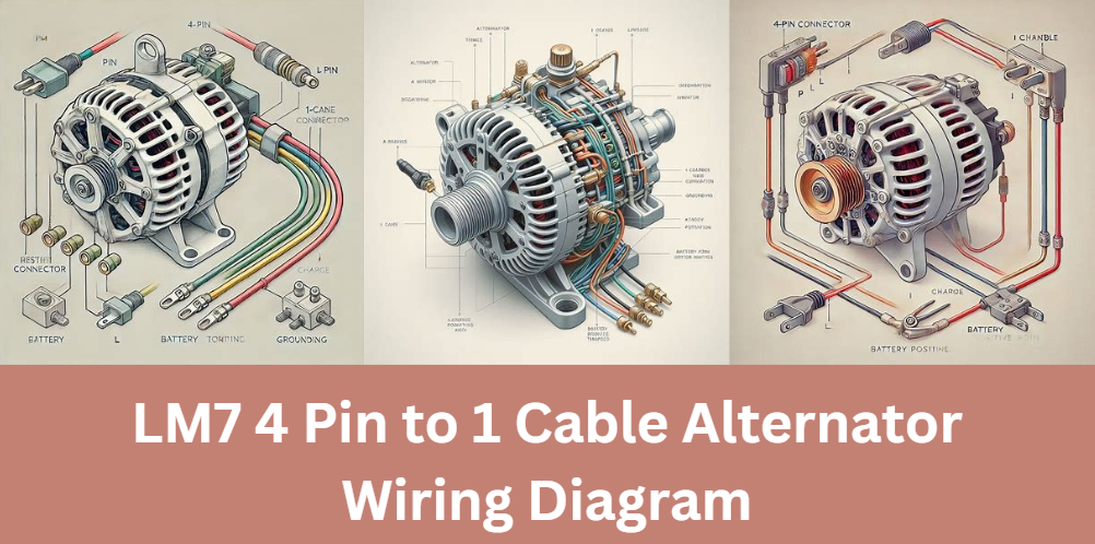
Understanding the LM7 Alternator 4-Pin Connector
The LM7 alternator uses a 4-pin connector, each terminal serving a unique purpose in the charging system:
| Pin | Function | Details |
|---|---|---|
| P (Phase) | Drives devices like tachometers. | Not essential in most conversions. |
| L (Lamp) | Controls the warning lamp and starts charging. | Essential for the 1-cable setup. |
| I (Ignition) | Supplies switched 12V power for excitation. | Often redundant in simpler configurations. |
| S (Sense) | Monitors battery voltage to regulate alternator. | Optional for basic setups. |
The L terminal plays a critical role in initiating the alternator’s operation, making it the focus of most 1-cable conversions.
Why Convert to a 1-Cable Setup?
Switching from the stock 4-pin wiring to a 1-cable configuration offers several benefits:
- Simplicity: Fewer wires mean easier installation and troubleshooting.
- Neater Appearance: Ideal for custom builds where aesthetics matter.
- Reliability: Reduces the chances of electrical issues by eliminating unnecessary connections.
By following the LM7 4 pin to 1 cable alternator wiring diagram, you can achieve a clean and efficient setup.
Step-by-Step Guide to the LM7 4 Pin to 1 Cable Alternator Wiring
Tools and Materials Needed
Before starting, gather the necessary tools:
- Multimeter
- Wire strippers and crimpers
- 470-ohm resistor (1/2 watt)
- Sufficiently gauged wiring
- Electrical tape or heat shrink tubing
Step 1: Identify and Label the Pins
Locate the 4-pin connector on your LM7 alternator and identify the terminals: P, L, I, and S. Use a multimeter if needed to confirm the wiring setup.
Step 2: Connect the L Terminal
The L terminal is essential for the 1-cable setup. Follow these steps:
- Use a 470-ohm resistor to connect the L terminal to a switched ignition source.
- Ensure the resistor is rated for the electrical load to avoid damaging the alternator’s regulator.
- Test the connection with a multimeter to confirm proper voltage flow.
Step 3: Secure the Charge Wire
Run a charge wire from the alternator’s output post to the battery’s positive terminal or the starter motor. Ensure the wire is appropriately gauged to handle the current flow.
Step 4: Ground the Alternator
The alternator typically grounds through its mounting bracket, but for added reliability, run a dedicated ground wire from the housing to a clean chassis ground point.
Step 5: Test the System
Start the engine and monitor the alternator’s output using a multimeter. The voltage should read between 13.8V and 14.5V.
Troubleshooting Common Issues
If your alternator doesn’t function correctly, consider these troubleshooting tips:
- Warning Light Stays On: Check the resistor connection at the L terminal.
- No Charging: Ensure the charge wire and ground connections are secure.
- Voltage Too Low: Verify the S terminal setup if used.
Advanced Tips for Optimal Performance
For enhanced performance, consider:
- Voltage Regulation: Use advanced external regulators for precise control.
- Aftermarket Accessories: Ensure your alternator setup supports additional electrical components like high-power lights or sound systems.
Conclusion
Converting your alternator using the LM7 4 pin to 1 cable alternator wiring diagram is a practical way to simplify your engine setup while maintaining reliability. By following this guide, you’ll have a streamlined, efficient electrical system ready for any LS engine swap or custom build.
For further insights, don’t forget to check out our related articles and share your experience in the comments. A cleaner, simpler alternator wiring setup is just a few steps away!
FAQs About LM7 4 Pin to 1 Cable Alternator Wiring Diagram
Can I use a universal wiring harness for the LM7 alternator conversion?
Yes, a universal wiring harness can be used for the conversion, but ensure it is compatible with GM LS engines and supports the 1-cable setup. Verify that the harness includes provisions for connecting the L terminal with a resistor and sufficient wire gauge for the charge wire.
What happens if I connect the alternator directly to the battery without the L terminal setup?
If the L terminal is not properly connected, the alternator may fail to start charging. This terminal acts as the excitation source, and without it, the alternator may remain dormant, resulting in no power output to charge the battery.
Is it necessary to upgrade the alternator when performing an LS engine swap?
Not always. The stock LM7 alternator is sufficient for most basic applications. However, if you are adding high-powered accessories like aftermarket sound systems, auxiliary lighting, or performance components, upgrading to a high-output alternator is recommended.
Can I reuse the stock alternator bracket during the conversion?
Yes, the stock alternator bracket can generally be reused. Ensure that it provides proper alignment and secure mounting for the alternator. For custom applications, aftermarket brackets designed for LS swaps may be more suitable.
What are the risks of using undersized wires in the alternator setup?
Using undersized wires can lead to overheating, voltage drops, and potential damage to the alternator or battery. It’s crucial to use appropriately gauged wires that can handle the current generated by the alternator to ensure safe and efficient operation.
Affiliated Posts Like LM7 4 Pin to 1 Cable Alternator Wiring Diagram
All You Need to Know About O-Ring Dia 10.6×1.85
The Ultimate Guide to 4772 N Lincoln Ave 60625-2010
Discover Everything About FarsiPlex: The Ultimate Platform for Persian Entertainment